- Name and define the three zones of the airways.
- Define a secondary pulmonary lobule and its appearance on high-resolution computed tomography (CT).
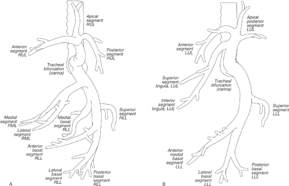
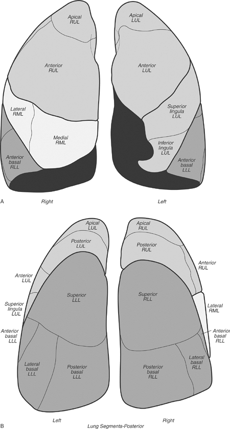
- List the lobar and segmental bronchi of both lungs.
- Identify the following structures on the posteroanterior chest radiograph:
- Lungs-right and left; right upper, middle, and lower lobes; left upper (including lingula) and lower lobes
- Pulmonary arteries-main, right, left, right interlobar, left lower lobe
- Airway-trachea, carina, main bronchi
- Fissures-minor, superior accessory, inferior accessory, azygos
- Aorta-ascending, arch (“knob”), descending
- Veins-superior vena cava, azygos, left superior intercostal (“aortic nipple”)
- Aortopulmonary window
- Right paratracheal stripe
- Junction lines-anterior, posterior
- Azygoesophageal recess
- Paraspinal lines
- Left subclavian artery
- Heart-right atrium, left atrial appendage, left ventricle, locations of the four cardiac valves
- Bones-spine, ribs, clavicles, scapulae, humeri
- Identify the following structures on the lateral chest radiograph:
- Lungs-right and left; right upper, middle, and lower lobes; left upper (including lingula) and lower lobes
- Fissures-major, minor, superior accessory
- Aorta-ascending, arch, descending
- Retrosternal clear space
- Veins-inferior and superior vena cavae, left brachiocephalic (innominate), pulmonary vein confluence
- Brachiocephalic (innominate) artery
- Airway-trachea, upper lobe bronchi, posterior wall of bronchus intermedius
- Heart-right ventricle, right ventricular outflow tract, left atrium, left ventricle, locations of the four cardiac valves
- Pulmonary arteries-right, left
- Posterior tracheal stripe
- Hemidiaphragms-right, left
- Bones-spine, ribs, scapulae, humeri, sternum
- Identify the following structures on chest CT:
- Lungs-right and left; right upper, middle, and lower lobes; left upper and lower lobes
- Fissures-major, minor, accessory (azygos, superior, and inferior)
- Pleura and extrapleural fat
- Airway-trachea, main bronchi, carina, lobar and segmental bronchi
- Heart-left ventricle, right ventricle, left atrium, right atrium, mitral valve, aortic valve, tricuspid valve, pulmonary valve, coronary arteries (left main, left anterior descending, left circumflex, right, posterior descending), coronary sinus
- Pericardium, including pericardial recesses
- Pulmonary arteries-main, right, left, right interlobar, segmental
- Aorta-ascending, arch, descending
- Arteries-brachiocephalic (innominate), common carotid, subclavian, axillary, vertebral, internal mammary, intercostal
- Veins-superior and inferior pulmonary, superior and inferior vena cavae, brachiocephalic, subclavian, axillary, internal jugular, external jugular, azygos, hemiazygos, left superior intercostal, internal mammary
- Bones-ribs, costochondral cartilages, clavicles, scapulae, sternum, spine
- Esophagus
- Thymus
- Thyroid gland
- Muscles-sternocleidomastoid, anterior and middle scalene, infrahyoid, pectoralis major and minor, deltoid, trapezius, infraspinatus, supraspinatus, subscapularis, latissimus dorsi, serratus anterior
- Aortopulmonary window
- Azygoesophageal recess
- Diaphragm
Anatomy is to physiology as geography is to history: it describes the theatre of events.
Jean Ferne (1497”“1558), On the Natural Part of Medicine
You’ve heard it before-what’s important in real estate holds true for understanding diseases of the chest: “location, location, location.” A good radiologist knows the anatomy, so don’t skip this chapter! This chapter is an abbreviated review of thoracic anatomy as seen on chest radiographs and computed tomography (CT) of the chest. As a result of differences in patient age, body habitus, positioning, inspiratory effort, exam technique, and many other factors, normal anatomic structures will vary in appearance on chest radiographs from exam to exam, patient to patient, and even breath to breath. Some structures are not seen consistently (posterior junction line), whereas others are seen on most exams (left upper lobe bronchus on lateral view). Showing the myriad different appearances of normal anatomic structures is beyond the scope of this chapter; they are learned by paying close attention to and identifying normal structures on thousands of chest radiographs.
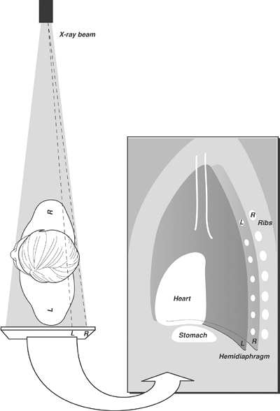
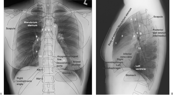
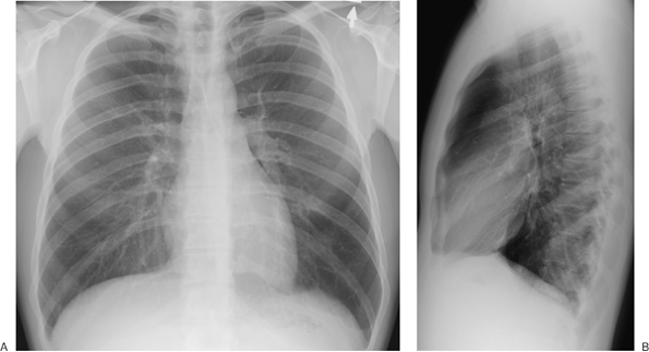
A frequent question of medical students and residents on their first rotation on a chest radiology service is: “How do you look at a chest radiograph?” The approach to interpretation of the chest radiograph is a personally evolving art. A person’s approach changes over time after seeing many chest radiographs. That answer doesn’t help the beginner, so a few general “chest radiograph rules” are offered in Table 1-1, and reference standards are presented in Table 1-2. Normal anatomic structures are labeled on posteroanterior (PA) and lateral chest radiographs (Figs. 1-1 and 1-2) and axial CT images (Figs. 1-3 and 1-4). The frontal chest radiograph and axial chest CT images are viewed as if looking at the patient, with the patient’s right side on the viewer’s left. Lateral radiographs are, by convention, viewed with the patient facing to the viewer’s left (patient’s left side closest to the imaging plate).
- When you have them, always look at both views (PA and lateral). To confirm that pathology is within the chest, it must usually be seen in the chest on both views.
- The right heart border is formed by the right atrium, and it is obscured by medial segment right middle lobe processes (disease limited to the lateral segment will not obscure the right heart border).
- The left heart border is formed mainly by the left ventricle and is obscured by lingular processes.
- The right diaphragm is usually 1.5 to 2.0 cm higher than the left.
- The diaphragm is obscured by lower lobe processes (unless only the superior segment of the lower lobe is involved).
- Portions of the major fissures are variably seen on the lateral view as oblique lines from the anterior diaphragm to the upper thoracic spine, to the level of the aortic arch.
- The minor fissure is on the right, separating the right upper lobe from the right middle lobe. It courses from the right hilum to the right lateral anterior chest wall and is variably seen on PA and lateral chest radiographs.
- Normal hilar opacities are predominantly caused by the pulmonary arteries and should be symmetric in size and density.
- The aortic arch, or “knob,” is above the left hilum. (Watch out for the right aortic arch variant!)
- The trachea is midline but may be deviated to the right or forward from a tortuous aorta.
- The costophrenic angles should be sharp on both views (sharp enough to pick your teeth with), except in patients with severe pulmonary emphysema, resulting in flattening of the hemidiaphragms.
- With good inspiratory effort, the size of the heart on the PA radiograph is normally less than or equal to 50% of the widest diameter of the thoracic cage.
- Right middle lobe and lingular processes are projected over the heart on the lateral view.
- A young healthy person can take a breath deep enough to inflate the lungs to the level of the 10th rib posteriorly (or the sixth rib anteriorly).
- Opacity of the lungs should be symmetric unless the patient is rotated.
- The stomach bubble is under the left hemidiaphragm. (Watch out for situs inversus.)
- Don’t forget to look at the bones and soft tissues.
| TABLE 1-1 INTERPRETATION OF THE CHEST RADIOGRAPH: “RULES” TO FOLLOW |
Zones of the Airways
The airways are composed of three zones. The conductive zone includes the trachea, bronchi, and nonalveolated bronchioles (air cannot diffuse through the well-developed wall). The transitory zone has both conductive and respiratory functions and consists of respiratory bronchioles, alveolar ducts, and alveolar sacs. The respiratory zone consists of alveoli. The primary function of this zone is the exchange of gases between air and blood.
Lung Architecture
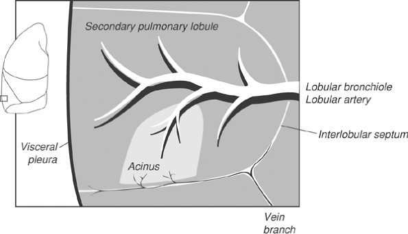
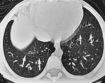
The primary pulmonary lobule consists of all alveolar ducts, alveolar sacs, and alveoli, together with their accompanying blood vessels, nerves, and connective tissues distal to the last respiratory bronchiole. This unit is too small to be seen radiologically. The secondary pulmonary lobule is the smallest discrete portion of the lung that is surrounded by connective tissue septae, and it is composed of three to five terminal bronchioles with their accompanying transitory airways and parenchyma (Fig. 1-5). A secondary pulmonary lobule contains 30 to 50 primary lobules, is polyhedral in shape and 1.0 to 2.5 cm in diameter, and can be appreciated on thin-section (1- to 2-mm) images of the lung. A pulmonary acinus is also an anatomic unit, defined as that portion of lung distal to the terminal bronchiole, comprising the respiratory bronchioles, alveolar ducts, alveolar sacs, and alveoli. Typically, six to 12 acini are grouped together in a secondary pulmonary lobule (1).
TABLE 1-2 SIZE AND DENSITY RATIOS ON THE PA CHEST RADIOGRAPH
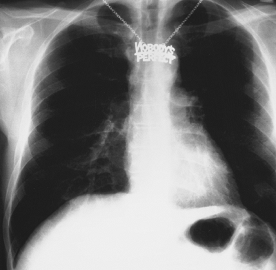
The retrosternal line is a bandlike opacity along the lower half or third of the anterior chest wall. Because the left lung does not contact the anterior portion of the left thoracic cavity at this level, the heart with its epicardial fat occupies this space.The posterior wall of the IVC is visible just before it enters the right atrium. The ascending aorta projects slightly superior and posterior to the right ventricular outflow tract. These structures are distinguished as discrete bulges on approximately 10% of lateral chest radiographs. The right pulmonary artery is seen on end as a round or oval structure anterior to the bronchus intermedius. The left pulmonary artery has an arcuate contour and courses superior and then posterior to the orifice of the left upper lobe bronchus (it can be likened to a miniaturized version of the transverse aortic arch).At the hilum, the right upper lobe bronchus is superior to the left upper lobe bronchus, and the posterior wall of the bronchus intermedius is seen as a thin opaque stripe between the two and intersecting the left upper lobe bronchus. Often, only the left upper lobe bronchus (and not the right upper lobe bronchus) is seen on the lateral view. The posterior wall of the bronchus intermedius should be no thicker than 3 mm. The most common causes of thickening are pulmonary edema and variation in patient positioning, but malignancy can also result in thickening.Several methods can be used to localize the right and left hemidiaphragms on the lateral chest radiograph (Fig. 1-16). On the standard left lateral chest radiograph, the right ribs are projected behind the left and appear larger because of magnification (unless the patient is not in a true left lateral position). Occasionally, the diaphragm can be followed out to its respective ribs. The stomach bubble is under the left hemidiaphragm (unless the patient has situs inversus). Pathologic processes obscuring only one hemidiaphragm on the PA view will confirm which diaphragm is being obscured by the same pathology on the lateral view. The right diaphragm will often be seen extending more anteriorly than the left hemidiaphragm,because the left hemidiaphragm will be partially obscured by the heart anteriorly. In some cases, however, none of these methods work, and which hemidiaphragm is which cannot be determined.Chest Radiology ConceptsThe chest radiograph is really more of a “lung radiograph.” It is not optimized for examination of the mediastinum or osseous structures. Nonetheless, how do you tell if the chest radiograph is adequately exposed? Ideally, there is a balance between overexposure (good for seeing the mediastinum) and underexposure (good for seeing the lungs). This balance is generally reached when the vertebral disc spaces are just barely visible. On hard-copy film, overexposure is better than underexposure, because you can see the darker areas under a bright light (copy films cannot be bright-lighted, as information has been lost in copying). With underexposure, information is irretrievably lost. With digital radiography systems, this is less of a problem.Was the film exposed during optimal inspiration? The degree of inspiration is limited in obese patients, or in patients with intra-abdominal mass effect, such as ascites, especially when imaged in the supine position. In general, expiratory films demonstrate more “doming” of the diaphragm, causing the apex of the heart to project below the left lung”“diaphragm interface. The lungs are more dense and the blood vessels more crowded together. If you judge that the inspiration is poor or limited, be cautious and do not overinterpret; this is particularly true for patients with suspected mild pneumonia or congestive heart failure.Extrapericardial fat pads vary in size from patient to patient and may result in relatively radiolucent opacities in the cardiophrenic angles that can obscure the lower inch or so of the heart border(s). When present, they can be visible on either frontal or lateral views or on both views, and they can be very large.Reference standards are used in making judgments of abnormality either clinically or radiologically. External reference standards are equivalent to experience. If you see enough examples, you will eventually get good at it. This is not much help to the novice. Four types of internal reference standards can be used by the novice: time (interval change, which allows instant judgment as to activity or chronicity); symmetry (paired structures, such as ribs, should look alike); continuum disturbance (similar structures, such as ribs or vertebral bodies, should show a progressive change); and ratios (density and size-density ratios require a well-exposed film, size ratios do not). Size and density ratios are outlined in Table 1-2. These ratios are for everyday use and will quickly become instinctive. When all else fails, remember that “nobody’s perfect” (Fig. 1-17), neither you nor the patient!.
Size
Cardiothoracic The heart diameter should be half or less than half of the chest diameter. An easy way to eyeball this-assuming the spine is straight and in the middle of the chest-is to see if the heart to the right of the midline fits between the left heart border and the left ribs.
Aortopulmonary The left pulmonary artery, as it passes over the left main bronchus, should be less than the width of the aortic knob. The aortic arch is approximately 3 cm above the carina in adults until the aorta begins to get tortuous. The left pulmonary artery is approximately 3 cm down the left main bronchus then ascends up and out at approximately 45 degrees.
Azygotracheal The azygos vein, if visualized (at the right tracheobronchial angle), should be no wider than approximately one half the width of the trachea, and its height should be no greater than the width of the trachea.
Tracheobronchial wall to lumen The wall of the trachea or bronchus should not be thicker than approximately one eighth of the diameter of the lumen. The tracheal diameter should be equal on the PA and lateral views and should be less than the width of a vertebral body.
Right lower lobe artery to trachea The right lower lobe pulmonary artery should not be wider than the width of the tracheal lumen.
Hilar height The left hilus should be approximately 2 cm higher than the right, because the left pulmonary artery has to go over the left main bronchus.
Arteriobronchial An artery and its accompanying bronchus should be the same size (seen best “end-on”).
Density
Cardiohepatic The heart should be about half as dense as the middle of the liver (it’s about half as thick). This reference requires good exposure. Beware the “ivory heart” of left lower lobe collapse.
Intracardiac The heart should be the same density on each side of the spine.
Intrahepatic The top of the liver should be about half as dense as the middle, because it’s about half as thick, provided the diaphragm domes normally.
Right paratracheal”“aortic The density to the right of the trachea at the level of the aortic arch should never be as great or greater than the density of the aortic knob.
Hilar The hila should be the same density (they are composed of the same vascularity).
P.5
P.6
Tracheobronchial Anatomy
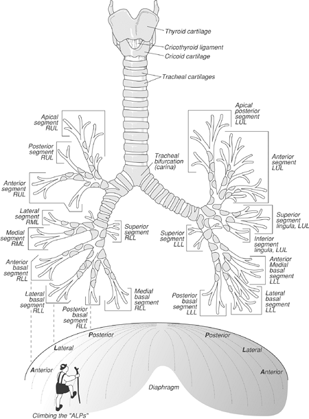
The intrathoracic trachea is 6 to 9 cm in length (2) and enters the thorax 1 to 3 cm above the level of the suprasternal notch. The upper limits of normal for coronal and sagittal tracheal diameters in adults on chest radiography are 21 and 23 mm, respectively, for women, and 25 and 27 mm for men (3). The trachea has 15 to 20 C-shaped rings of hyaline cartilage (absent in the posterior membranous trachea), which provide the rigidity that prevents the trachea from collapsing (4). The trachea divides into right and left mainstem bronchi at the carina. The right main bronchus, about 2.5 cm in length, is shorter, wider, and more nearly vertical than the left. Because it is almost in a direct line with the trachea, foreign objects passing through the trachea usually enter the right main bronchus.
The lobar and segmental branching patterns of the mainstem bronchi and pulmonary lobes and segments are shown in Figures 1-6, 1-7, 1-8. There are ten segmental bronchi on the right. On the left, apicoposterior and anteromedial combinations result in eight left segmental bronchi, although some anatomists refer to ten segments on the left. Segmental bronchi divide, and after six to 20 divisions they no longer contain cartilage in their walls and are referred to as bronchioles. The bronchioles divide, and the last of the purely conducting airways is referred to as the terminal bronchiole. Beyond the terminal bronchioles lie the acini, the gas exchange units of the lung. Subsegmental bronchi can routinely be identified with thin-section CT.
Pulmonary Hila
On chest radiography, normal hilar opacities are composed of both major bronchi and blood vessels, but most of what you see are pulmonary arteries. The left hilus is higher than the right, as seen on the PA chest radiograph, because the left pulmonary artery is higher than the right. The right upper lobe bronchus is higher than the left upper lobe bronchus, as seen on the lateral chest radiograph, because the right upper lobe bronchus is eparterial (above the artery); the left lower lobe bronchus is hyparterial (below the artery). The transverse diameter of the lower lobe arteries should normally be 9 to 16 mm (1). Bronchi and pulmonary arteries branch out from the hilum together, whereas pulmonary veins drain to the heart, separate from the bronchi and arteries. In the outer two thirds of the lungs, arteries cannot be distinguished from veins on chest radiography. More centrally, the orientations of the arteries and veins differ. The inferior pulmonary veins draining the lower lobes run more horizontally and are directed toward the left atrium, whereas the lower lobe arteries are oriented more vertically. In the upper lobes, the arteries and veins show a similar gently curving vertical orientation; the upper lobe veins lie lateral to the arteries and can sometimes be traced to the superior pulmonary vein. There are right and left superior and inferior pulmonary veins, which drain into the left atrium. Lymph flows to the hilum via lymphatic channels that are found in a subpleural location and within the interlobular septae.
Fissures
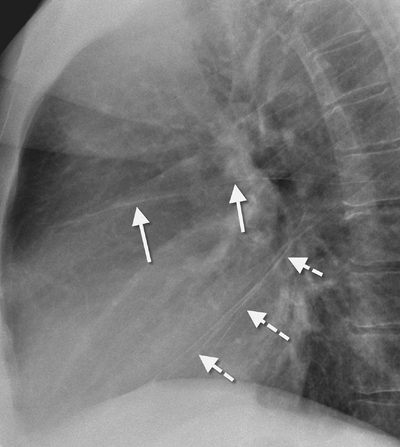
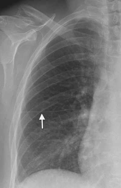
The major (oblique) fissures run obliquely forward and downward from approximately the level of the fifth thoracic vertebral body to the diaphragm and divide the lungs into upper and lower lobes (Fig. 1-9). The right major fissure is more oblique, ends further forward inferiorly (more anterior on the lateral chest radiograph), merges with the right hemidiaphragm, and joins the minor fissure. The minor (horizontal) fissure separates the right middle from the right upper lobe and fans out forward and laterally from the right hilus (Fig. 1-10). It is unusual to be able to trace both fissures in their entirety on chest radiographs. Fissures are often “incomplete” and only partially separate lobes.
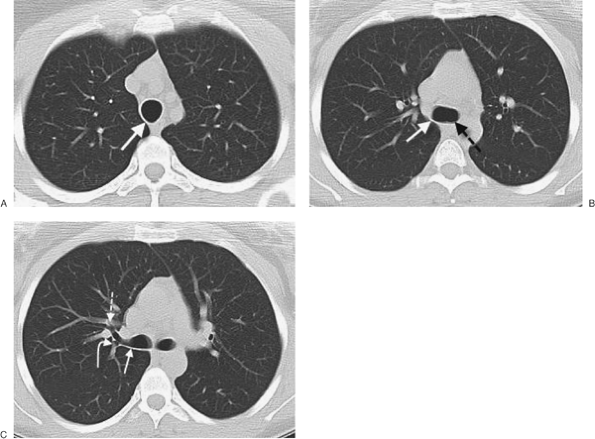
On CT scans, the region of the major fissures can usually be seen as a band of avascularity. The fissure itself may be invisible, or it may be seen as a poorly defined or well-defined band of density, depending upon slice thickness. The position of the minor fissure can be inferred on CT scans from the large oval deficiency of vessels on one or more sections at the level of the bronchus intermedius.
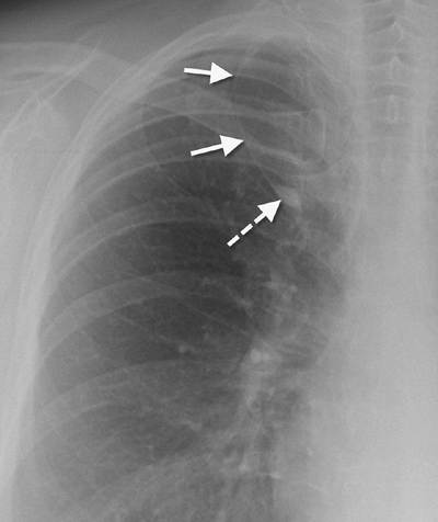
Numerous accessory fissures may be identified as normal variants. Approximately 1% of the population will have an accessory azygos fissure, creating an accessory azygos lobe in the right superomedial lung (Fig. 1-11). The azygos fissure contains the azygos vein (which, in the case of an azygos fissure, is always located higher than its usual location in the tracheobronchial angle) within its lower margin, and it is easily seen on chest radiography because it contains four pleural layers (two visceral and two parietal). The left minor fissure separates the lingula from the other left upper lobe segments. The superior accessory fissure separates the superior segment from the basal segments in either lower lobe, is horizontally oriented, and is seen below the level of the minor fissure on the right. The inferior accessory fissure separates the medial basal segment from other basal segments in either lower lobe, and it runs obliquely upward and medially toward the hilus from the diaphragm (Fig. 1-12).
Mediastinal Blood Vessels
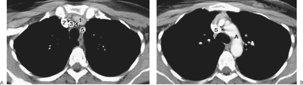
The thoracic aorta has ascending, transverse (arch), and descending portions. The ascending portion becomes more prominent as a patient ages. On a frontal chest radiograph, the arch is seen to the left of midline as a smooth “knob.” The descending portion gradually moves from a position to the left of the vertebral bodies to an almost midline position before exiting the chest through the aortic hiatus in the diaphragm. The three major aortic branches, lying anterior to and to the left of the trachea, are (in order from the patient’s right to left) the brachiocephalic (innominate) artery, the left common carotid artery, and the left subclavian artery.
The superior vena cava (SVC) is seen in the right paratracheal area, typically representing the right superior mediastinal contour. In 0.3% to 0.5% of people without congenital heart disease, a left superior vena cava is present (5). A left SVC arises from the junction of the left jugular and subclavian veins and travels vertically through the left mediastinum, usually emptying into the coronary sinus, which drains into the right atrium. Patients with a left SVC may also have a right SVC, which is typically smaller than usual.
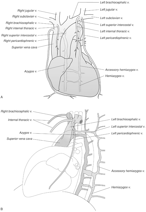
The azygos vein courses anterior to the spine, either behind or to the right of the esophagus, until it arches anteriorly to join the posterior wall of the SVC. The azygos vein usually remains within the mediastinum and occupies the right tracheobronchial angle (in the case of an azygos lobe, the azygos vein traverses the lung before entering the SVC). The hemiazygos and accessory hemiazygos veins lie against the vertebral bodies, posterior to the azygos vein. The accessory hemiazygos vein drains into the left superior intercostal vein, which arches around the aorta at the junction of the arch and the descending portion, and joins the left brachiocephalic vein (this contact with the aorta forms the so-called “aortic nipple” occasionally seen on the PA chest radiograph). Venous anatomy is illustrated in Figure 1-13. In patients with absence of the inferior vena cava (IVC), the azygos vein forms the venous conduit draining the “IVC blood” back to the heart (hepatic veins then drain into the right atrium, not into the IVC). In such cases, the azygos vein will be very large, as seen on the PA chest radiograph in the tracheobronchial angle, and can resemble adenopathy.
The main pulmonary artery is anterior and to the left of the ascending aorta. The left pulmonary artery arches higher than the right and passes over the left main bronchus.
Mediastinal Spaces, Lines, Stripes, and Borders
The aortopulmonary window is the space under the aortic arch and above the left pulmonary artery. The ligamentum arteriosum (remnant of the ductus arteriosus) and recurrent laryngeal nerve traverse this space (a mass in the aortopulmonary window can involve the recurrent laryngeal nerve and result in hoarseness). The subcarinal space is inferior to the carina, bounded by the main bronchi, and is a site where adenopathy occurs. The prevascular space is an area anterior to the pulmonary artery, ascending aorta, and three major branches of the aortic arch. This space lies between the two lungs and is bounded anteriorly by the chest wall. Where the lungs approximate, there is no prevascular space but rather an anterior junction line. Within the prevascular space is the left brachiocephalic vein, internal mammary arteries, lymph nodes, thymus, and phrenic nerve. The retrocrural space (aortic hiatus) is the space bounded by the diaphragmatic crura and the spine. Structures that pass through this area can be thought of as the “birds of the mediastinum”: azygos vein (“azygoose”), hemiazygos vein (“hemiazygoose”), and thoracic duct (“thoracic duck”). The esophagus (“esophagoose”) is another of the birds of the mediastinum; however, it passes through the esophageal hiatus.
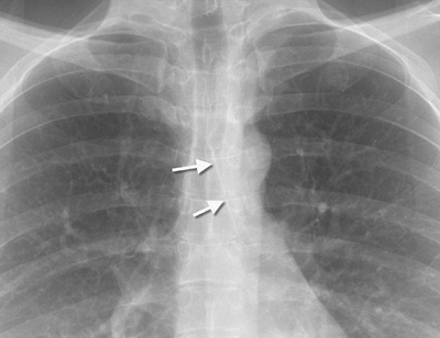
The right and posterior tracheal stripes are formed where the lung contacts the trachea to the right and posteriorly, and they are normally 3 mm wide or less. The anterior junction line is where the right and left lungs approximate above the level of the heart and below the manubrium (Fig. 1-14). It is composed of four layers of pleura (both the parietal and visceral layers from each hemithorax), may reach the level of the clavicles superiorly, and is not always evident on chest radiography because of intervening fat and/or thymus. Deviation of the anterior junction line suggests a mass or shift of the mediastinum. The posterior junction line is where the two lungs meet behind the trachea and heart. Unlike the anterior junction line, it extends to the lung apices, projecting above the clavicles (Fig. 1-15). It is also composed of four pleural layers, and bulging of the border is normal only in the area of the azygos vein or aortic arch. The azygoesophageal line, seen on the frontal chest radiograph below the aortic arch, is where the right lower lobe makes contact with the right wall of the esophagus and the azygos vein as it ascends next to the esophagus. This portion of lung is known as the azygoesophageal recess and the interface is known as the azygoesophageal line. The upper few centimeters of the azygoesophageal line are always straight or concave toward the lung in adults; a convex shape indicates a subcarinal mass. Paraspinal lines are stripes of soft tissue density, parallel to the left and right margins of the spine, formed by the approximation of the lung with the spine. They are usually less than 1 cm in width. Aortic tortuosity will contribute to the thickness of the left paraspinal line.
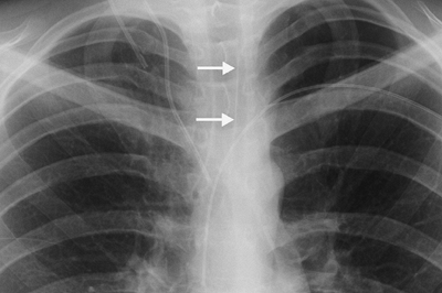
Above the aortic arch, the left paratracheal shadow is caused by the left carotid and subclavian arteries and the left jugular vein. The outer margin of the left tracheal wall is almost never outlined because the trachea is not contiguous with the lung (it is separated by the aorta and great vessels). Below the arch, the left mediastinal border is formed by the aortic pulmonary pleural stripe, the main pulmonary artery, and the heart. The right mediastinal border is formed by the right brachiocephalic vein, SVC, and right atrium. A right paratracheal stripe is seen in approximately two thirds of normal subjects through the right brachiocephalic vein and SVC.
Diaphragm
The diaphragm can normally have a smooth or a scalloped contour. The right hemidiaphragm is higher than the left in approximately 88% of people by 1.5 to 2.0 cm. The left is higher than the right in approximately 3% of people but by less than 1 cm. The hemidiaphragms are at the same level in approximately 9% of people (6). Eventration (incomplete muscularization of the diaphragm) refers to a thin membranous sheet replacing what should be muscle, causing a smooth hump on the contour of the diaphragm (frequently the anteromedial right diaphragm). Total eventration, more common on the left than on the right, results in elevation of the whole hemidiaphragm.
Lateral Chest Radiograph
What follows is an abbreviated review of chest anatomy as seen on the lateral chest radiograph. A complete review of the left lateral chest radiograph was published in 1979 by Proto and Speckman (7).
The brachiocephalic (innominate) artery arises anterior to the tracheal air column. Its posterior wall can be seen as a gentle S-shaped interface crossing the tracheal air column. The left brachiocephalic vein often forms an extrapleural bulge behind the manubrium. The posterior border of the right brachiocephalic vein and the SVC can occasionally be identified curving downward in much the same position and direction as the brachiocephalic artery, but they are sometimes traceable below the upper margin of the aortic arch. The convex margin of the innominate artery”“right subclavian artery complex projects through the tracheal air column and merges with the posterior aspect of the right brachiocephalic vein”“SVC to form a sigmoid-shaped interface.
The course of the trachea is straight or bowed forward in patients with aortic tortuosity. The carina is not visible on the lateral chest radiograph. The anterior wall of the trachea is visible in only a minority of people. The posterior wall of the trachea is usually visible, because lung often passes behind the trachea, forming the posterior tracheal stripe (seen in 50% to 90% of adults). This stripe is normally narrower than 3 to 4 mm. If there is little or no air in the esophagus, this stripe is formed by the full width of a collapsed esophagus (leading to a band of density 1 cm or wider) and is then called the tracheoesophageal stripe.